There are several issues with laser guided boring bar systems that I have trouble getting around.
- The laser must be adjusted often as the cut goes deeper into the vessel.
- The laser produces a large dot instead of precise point to indicate where the cutting edge is.
- Once the laser falls off the edge of the vessel you lose all reference to where the cutter is.
- You can't really see where the cutter is, there is just reference point relative to the cutting edge that you have to imagine.
- Lasers only work on solid round objects. Off-center turning, or voids in the vessel make it useless.
- Needs batteries or power cord. Power cords can be dangerous around spinning lathes.
- If you are using a steady rest, it can interfere with the laser beam so a portion of the vessel you are doing blind.
 A few years ago I was making vases on which I carved one side and not the other.
So, I wanted to make the interior off-center from the exterior so that one side had thickness to carve into and the other side was thinner.
A laser based hollowing system would work since there was no constant exterior surface to focus the laser on. So, I developed a template based boring system.
A few years ago I was making vases on which I carved one side and not the other.
So, I wanted to make the interior off-center from the exterior so that one side had thickness to carve into and the other side was thinner.
A laser based hollowing system would work since there was no constant exterior surface to focus the laser on. So, I developed a template based boring system.
With my system, the process is so much easier and relaxing because while boring,
you don't have to imagine where the cutting edge is. You can directly see exactly how thin the wall is where the cutter is cutting.
You only have to adjust it once and then you can cut entire vessel. Though you still may have to stop regularly to remove shavings if you don't have enough voids in your workpiece.
There is no need for batteries, or power cords. It works on any shape vessel even with voids.
And the steady rest is integrated into the system.
Plus there are a few added benefits: - You get extra counter space on the template platform to lay tools.
- You get a paper template of your work (suitable for framing) so future duplication is possible.
The three key principles
There are three key principles which make this all possible.
Create template based on exterior profile of vessel
So where does the template come from? You could print it out from computer CAD software. But then you have to position it exactly relative to the vessel on the lathe. Besides, the exterior is most likely an artistic shape that you just created on the lathe.
Well, the boring bar system can be used to trace the exterior shape of the vessel onto a piece of paper. All you have to do is replace the laser with a pen and place a probe in the end of the boring bar.
If the pen is directly above the probe, the resulting outline will be sized and positioned perfectly above the vessel. See the next section for a description of how to get the pen positioned correctly.
Use a vertical reference to position the pen and pointer
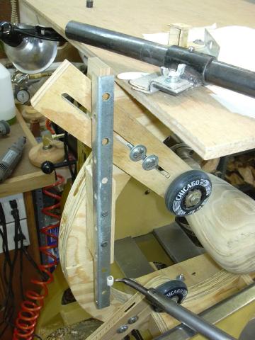
I use a vertical piece of angle iron attached to the side of my steady rest to position the pen and pointer.
If it is exactly vertical, and the boring bar is level, then the orientation will be correct throughout the possible positions of the boring bar during boring.
The pen is used to create the template and the pointer is used to follow the template line during boring.
Make the pointer larger than the cutter to specify wall thickness
Ok, now we have a line directly above the exterior profile of the vessel. If we make a pointer the exact shape and size of the cutter, and cut away the interior of the vessel until the pointer touches the line on the template,
well... we would have an infinitely small wall thickness. This is generally a bad idea. We want a uniform wall thickness along the entire profile of the vessel.
You could manually draw another parallel line next to the jig drawn one. But I find it easier to just make a larger pointer. If the pointer is 1/4 inch larger than the cutter profile, then the resulting wall thickness will be 1/4 inch if the pointer comes up to and touches the template line.
To make a different wall thickness I use a different size pointer.
I have a set of various sized pointers (made out of those pre approved plastic credit cards that come in the mail all the time) for each profile of cutter I use.
Positioning the pointer directly above the cutting tool takes another step as described below.
How it's done
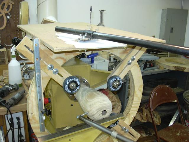
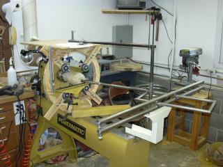
 First you need a way to attach a platform above the turning. I built a custom steady rest with a bracket to the top to hold a piece of plywood for the platform. I really don't use the steady rest much except for this purpose. So, it does not have to be as sturdy as a real steady rest would be. In fact since these pictures were taken, I remove the wheels and use it exclusively for template hollowing.
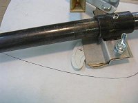
The steady rest frame also holds a vertically mounted positioning index (angle iron).
First you need a way to attach a platform above the turning. I built a custom steady rest with a bracket to the top to hold a piece of plywood for the platform. I really don't use the steady rest much except for this purpose. So, it does not have to be as sturdy as a real steady rest would be. In fact since these pictures were taken, I remove the wheels and use it exclusively for template hollowing.
The steady rest frame also holds a vertically mounted positioning index (angle iron).
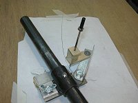 The laser assembly is replace with an apparatus that holds a pen ink refill and the pointer card. The apparatus allows for easy repositioning of both the pen and pointer relative to the support arm.
 To position the pen, Place a probe in the end of the boring bar with a point to follow the contour of the vessel. Place that point against the vertical positioning index and move the pen to to be at the point directly above the end of the probe.
Be sure the boring bar is completely level before aligning the jig. Adjusting the height of the tool rest will tip the boring bar assembly up or down and destroy the alignment.
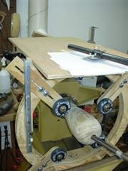
Now with a piece of paper taped to the platform, trace the contour of the vessel. I use a weight setting on the top of the pen to hold the pen down on the paper.
To position the pen, Place a probe in the end of the boring bar with a point to follow the contour of the vessel. Place that point against the vertical positioning index and move the pen to to be at the point directly above the end of the probe.
Be sure the boring bar is completely level before aligning the jig. Adjusting the height of the tool rest will tip the boring bar assembly up or down and destroy the alignment.
Now with a piece of paper taped to the platform, trace the contour of the vessel. I use a weight setting on the top of the pen to hold the pen down on the paper.
Now you have a tracing of the contour of your vessel. You may have to manually extend the line to complete the bottom of the vessel since the exterior profile near the bottom of the vessel is not turned yet (that's where the chuck for faceplate is).
 To position the pointer, remove the probe from the end of the boring bar and replace it with the cutter you wish to use. remove the pen and insert a pointer card which is larger than the cutter (as much larger as your intended wall thickness).
Now, you want to place the cutter directly under the pointer card so that when the pointer touches the line on the template, the cutter is the intended wall thickness away from the line. To do this I use various cylinders slipped over the side of the vertical positioning index.
This way when the pointer card touches the corner of the positioning index, the cutter will simultaneously be touching the cylinder directly below. This places the cutter informally inside the pointer card so that no matter what side of the cutter is approaching the side of the vessel, the wall thickness is maintained.
Move the cutter around the profile of the cylinder and the pointer will just glide around the narrow edge of the vertical piece of steel. This orientation will be maintained no matter what angle the boring bar is positioned in. The cutter will always be the same horizontal distance from any side of the pointer card.
To position the pointer, remove the probe from the end of the boring bar and replace it with the cutter you wish to use. remove the pen and insert a pointer card which is larger than the cutter (as much larger as your intended wall thickness).
Now, you want to place the cutter directly under the pointer card so that when the pointer touches the line on the template, the cutter is the intended wall thickness away from the line. To do this I use various cylinders slipped over the side of the vertical positioning index.
This way when the pointer card touches the corner of the positioning index, the cutter will simultaneously be touching the cylinder directly below. This places the cutter informally inside the pointer card so that no matter what side of the cutter is approaching the side of the vessel, the wall thickness is maintained.
Move the cutter around the profile of the cylinder and the pointer will just glide around the narrow edge of the vertical piece of steel. This orientation will be maintained no matter what angle the boring bar is positioned in. The cutter will always be the same horizontal distance from any side of the pointer card.
 Now hollow away until the pointer card comes in contact with the template line. It's really that simple (once it's set up).
The card rides just above the surface of the platform so I place a bright light directly above the lathe and watch the shadow cast by the pointer as I approach the template line.
Now hollow away until the pointer card comes in contact with the template line. It's really that simple (once it's set up).
The card rides just above the surface of the platform so I place a bright light directly above the lathe and watch the shadow cast by the pointer as I approach the template line.
|