Pipe Joint Template Online Software Manual and Procedure Tutorial
 This Pipe Joint Template Online Software is made available for individual private use.
Disclaimers: This software was originally written to help me to create an inexpensive dust control system in my workshop.
However, the uses for such a program could include other disciplines. The procedure described here is written for a small workshop using PVC piping for dust collection.
If anyone wanted to use this software for any other purpose, they would need to adapt the instructions for their needs. Any piping installation that
transports liquids, pressurized gas or any toxic gas must follow industry standard guidelines for plumbing that are not discussed here.
The example usage of the software here uses PVC pipe to demonstrate how the templates are used. Anyone using PVC must understand the
toxic nature of PVC. When heated or cut, PVC pipe gives off toxic gases that should not be breathed.
Here is an example of how the Template software can be used.
Pipe Joint Template Online Software will calculate and draw a template that can be used to find the junction of two pipes (or cylinders) and transfer that junction location to the surface of the pipe using a printable template.
The assumption is made that there is one main pipe being joined by an equal or smaller sized branch pipe feeding into the main pipe.
Before running the software, the dimensions of the pipes and angle of attachment must be known.
The software will ask for the external diameter of both pipes and the wall thickness of the branch pipe.
This information can be taken from measuring the pipes being used or from standard specification of the type of pipe being used.
The branch pipe must be equal or smaller in size than the main pipe. If standard off the shelf pipe fittings were used, the various angles available in 'T' type fittings are very limiting.
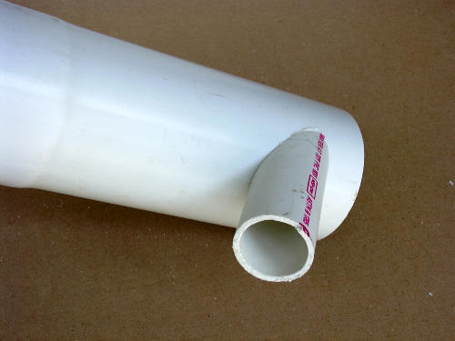
 In this example I will be joining a 1 1/2 inch Schedule 40 PVC pipe to a 4 inch PVC ASTM 2729 "Sewer and Drain (S&D)" pipe at a 60 degree angle.
This portion of the procedure uses this Pipe Joint Template Online Software.
Entering the data for this example:
The join angle defines angle at which the branch pipe joins the main pipe. A join angle of 90 deg. is a right angle and would make a standard 'T' joint.
A very small join angle would make the two pipes nearly parallel. Optimum air flow would require a join angle of less than 45 degrees. We will use 60 degrees in this example.
The main pipe has a diameter of 4.215 inches. The branch pipe has a diameter of 1.9 inches and a thickness of 0.145 inches.
 The last parameter needed by the software is 'lateral offset'. If lateral offset is zero, then both pipes centerlines will align. Lateral offset is the number of inches the branch pipe is moved to the left or right (negative or positive) of the centerline of the main pipe.
This feature would be useful if two different sized pipes that were running along flush with a wall or ceiling were to be joined. Then the lateral offset would be set to be equal to the differences in their radiuses. If too large an offset is specified, a warning message will inform the user of the largest offset allowed, which will make the side of the two pipes flush.
To make this example interesting, I will make a negative one inch offset joint.
The last parameter needed by the software is 'lateral offset'. If lateral offset is zero, then both pipes centerlines will align. Lateral offset is the number of inches the branch pipe is moved to the left or right (negative or positive) of the centerline of the main pipe.
This feature would be useful if two different sized pipes that were running along flush with a wall or ceiling were to be joined. Then the lateral offset would be set to be equal to the differences in their radiuses. If too large an offset is specified, a warning message will inform the user of the largest offset allowed, which will make the side of the two pipes flush.
To make this example interesting, I will make a negative one inch offset joint.
Pressing 'Submit' will calculate the templates and draw a low resolution copy of those templates on the right half of the screen. Clicking on any of these templates will show a full size version.
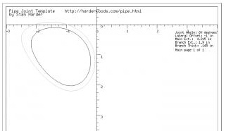
There is also a link below the 'Submit' button to show all templates on one webpage so they can all be printed. Note that the templates are created in such a way that they will be scaled on the monitor so they might look like some lines are missing, but they will print correctly.
When printing a template make sure that the browser page setup properties are set to not rescale the image. The templates will print at 100% scale on 8.5x11 paper. If the template is too large for one page of paper, it will be split across several pages. Alignment marks are provided in the corners of multiple page templates to aid the user in taping the pages together to make a large template.
Always check the templates by comparing a ruler to the scales printed on the template. If the inch markings on the printed scale does not match your ruler, then the template did not print correctly and should not be used.
|
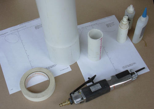
Once the templates are printed out, the tools needs are simple. Tape to hold the template to the pipe.
A saw: I use a air body saw, but a jig saw with a fine tooth blade could also work.
Not shown, but if you are not a perfect cutter, you will want either some coarse sand paper and/or a half round file.
Also, an appropriate bonding agent. I'm working with low pressure air so medium density Cyanoacrylate Glue (CA) glue will do fine.
Notice the debonder and accelerator in the photo. I never use CA without the debonder within reach.
|

|
|
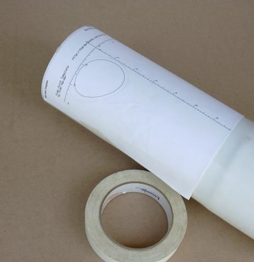
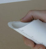
First the main pipe template is wrapped around the main pipe.
The axial scale is the ruler markings running vertically on the template.
The axial scale must be aligned with the length of the pipe.
Rotate the template on the pipe so that the axial scale line marks the direction the branch pipe will run.
The axial scale is such that at its zero point marks the point of intersection of the centerlines of the two pipes.
A ruler may be needed to find the zero marking if it is off the top of the template.
|

|
|
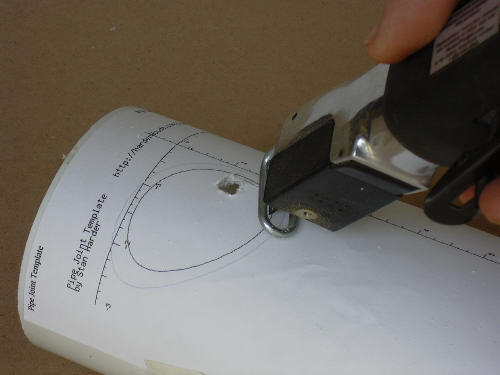
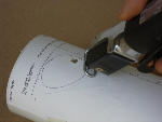
Cut just on the inside of the dark line holding the saw blade in the general direction that the branch pipe will eventually run.
I have drilled a hole to insert the blade of an air body saw to begin.
|
|
|
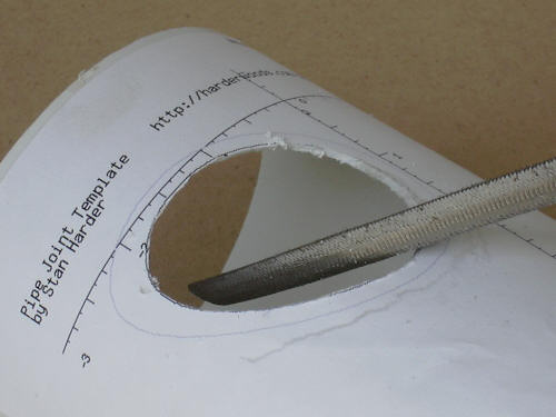
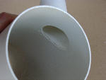
Any imperfections in the cut can be cleaned up with a half round file or coarse sand paper.
|
|
|
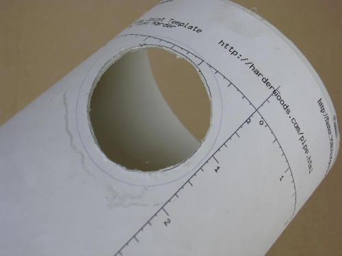
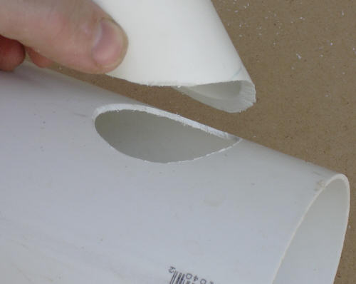
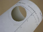
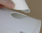
We now have a hole in the main pipe that coincides with the interior edge of the branch pipe when assembled.
The light line outside the cut is the outside diameter of the branch pipe.
|
|
|
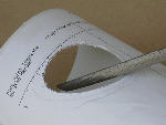
Now it's time to take the branch pipe template and wrap it around the branch pipe. Again, the axial scale markings indicate the distance from the intersection of the centerline of the two pipes.
The axial scale marks the side of the branch pipe pointing in the direction of the main pipe air flow.
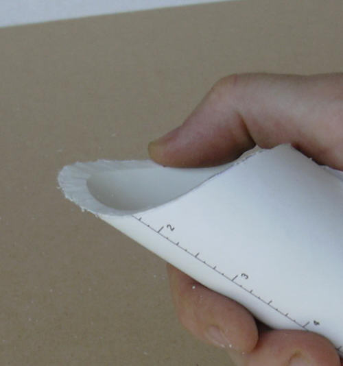
The dotted lines on the template will wrap around to the opposite side of the pipe and overlap each other. Note in the photo how the dotted lines overlap.
There is a dark line and a lighter line on this template that now wraps completely around the pipe. The lines should make two continuous loops around the pipe if the diameter of the pipe was specified correctly.
The dark line is the cut line for the external surface of the pipe and the light line indicates where the cut should exit the internal surface of the pipe.
|

|
|
Care must be taken to hold the saw at the correct angle so that the end surface of this pipe will fit flush against the surface of the main pipe.
|
|
|
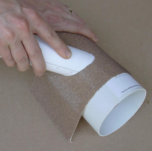
If the cut isn't exactly right, there is a way to clean up the cut. A piece of coarse sand paper can be wrapped around the main pipe and the branch line rubbed up and down the main pipe to clean up the cut.
|

|
|
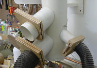
At this point the two pipes should fit fairly well. An exact fit is not needed for this application.
The medium thickness CA clue is a good gap filler.
|
|
|
Check the fit.
|
|
|
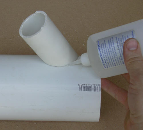
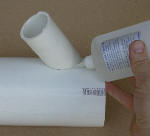
Make sure the surfaces are clean. Spray some CA accelerator around the hole in the main pipe.
Apply a bead of CA glue to the end surface of the branch pipe, and place in position.
|
|
|
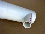
Another bead of medium CA around the outside and inside of the joint will make it quite sturdy.
|
|
|